
Dual-side foldable PV array
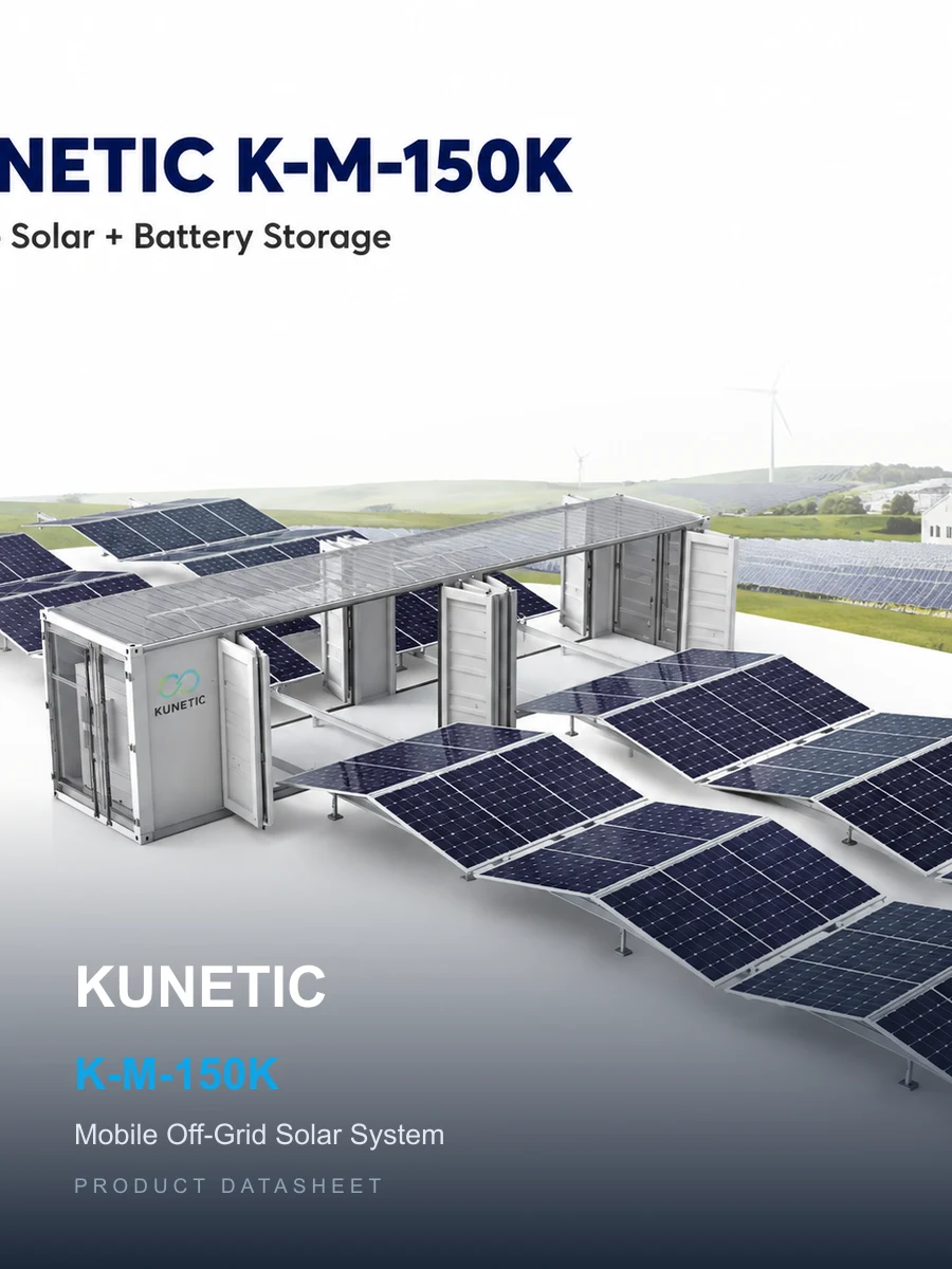
The array deploys from both sides of the container to create the operating PV field.
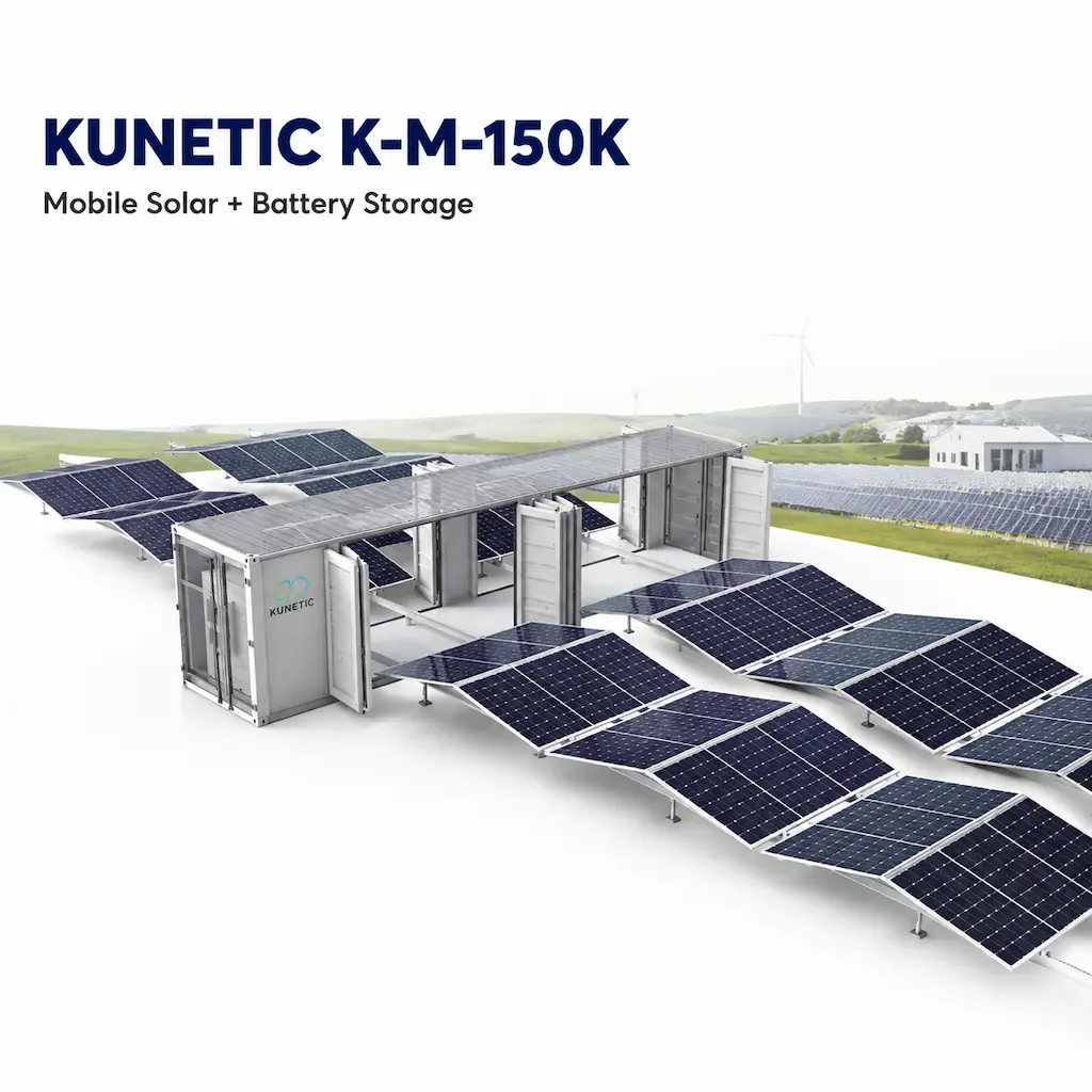
Mobile Solar + Battery Storage
The KUNETIC mobile off-grid solar system combines a foldable 152kWp PV array, rated three-phase AC output and standard LFP battery storage in one transportable container platform. It is intended for mining, construction, remote industrial and temporary power projects where permanent power infrastructure is unavailable or impractical. After the container is positioned and the rail system is prepared, the PV array unfolds on both sides. It can later be retracted for transport to another project. Four PV configurations and project-specific electrical options allow the system to be matched to site area, load requirements and target-market needs.
 150kW Rated AC Output
  152kWp PV Array Capacity
  261kWh Standard Battery Capacity
  12m Container Length
 Overview
Remote and temporary projects often need more than a fixed PV array. They need a power system that can arrive as one containerized asset, be deployed around a prepared site and leave when the work moves. The system combines a dual-side foldable PV array, a hybrid inverter, LFP battery storage and three-phase AC output. Buyers can select one of four PV configurations. Electrical settings, optional interfaces and market-specific certification are confirmed during project engineering.
Power for remote or temporary sites
Bring solar generation and battery storage to projects where permanent power infrastructure is unavailable or impractical.
A relocatable alternative to fixed PV construction
Retract the array, prepare the container for transport and redeploy the asset when the project location changes.
One project platform for PV, storage and AC output
Evaluate generation, battery capacity and three-phase output as one system rather than separate equipment packages.
A clearer match between PV size and site footprint
Choose among four PV configurations based on available area, solar resource and project requirements.
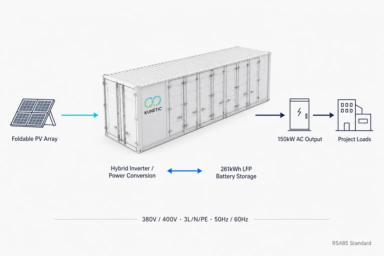
Foldable Deployment
The PV array is stored in the container transport form and opens on both sides after the unit is lifted into position and the rail system is prepared. Electric drive handles opening and closing. The final locking action is manual.
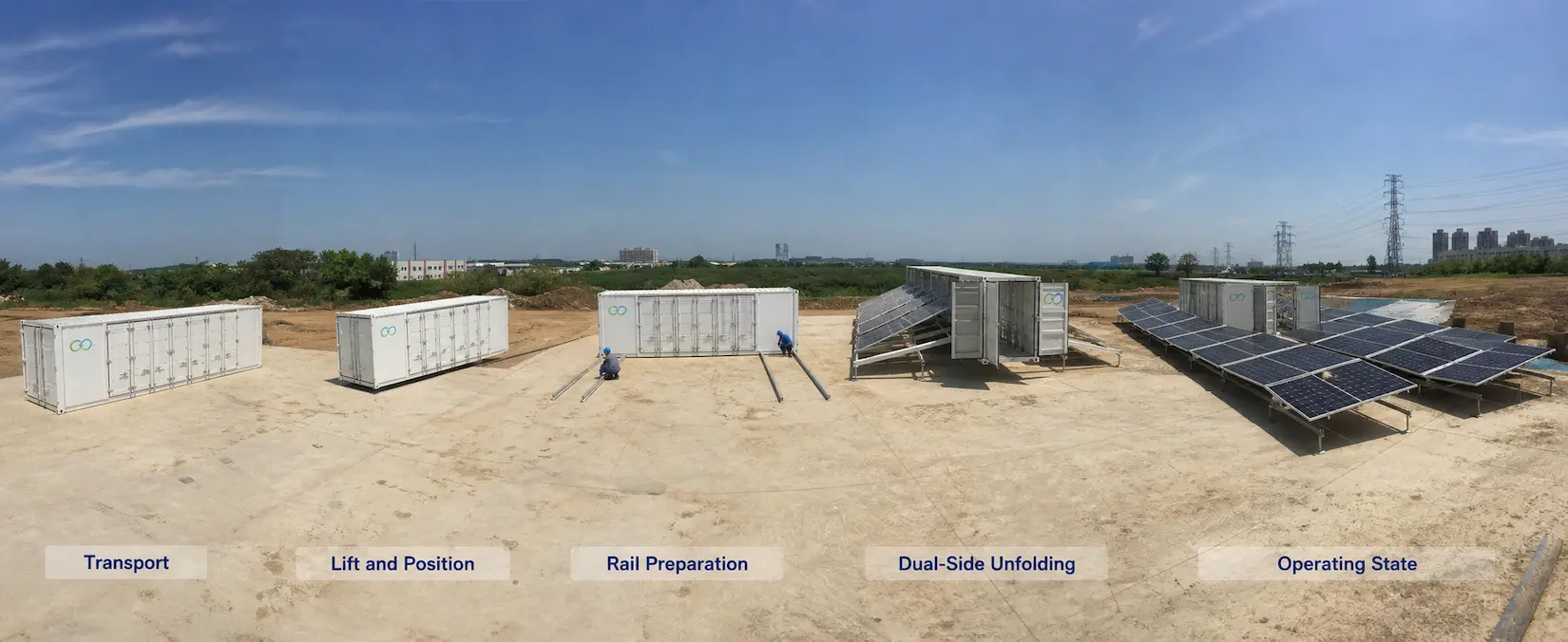
The array deploys from both sides of the container to create the operating PV field.
Electric drive moves the array structure. The locking mechanism remains manual.
Rail laying is documented as 15h and remains separate from mechanical unfolding.
This value applies after transport, site preparation, lifting and rail preparation. It does not include electrical connection, commissioning or full-site energization.
IP55 applies in the stowed state. The documented operating range is -20°C to +50°C, with level 9 wind resistance after deployment and salt-fog resistance stated as ≤C5.
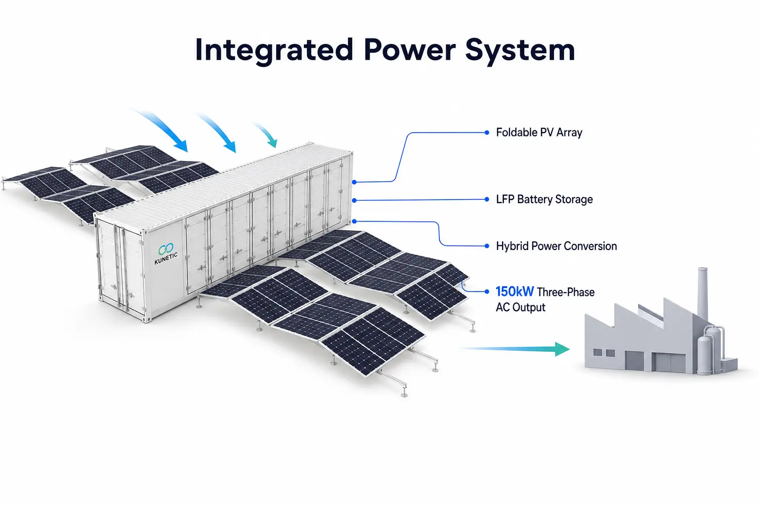
Integrated Power System
PV energy is converted through a hybrid inverter and coordinated with the LFP battery system before supplying project loads. The platform supplies three-phase AC at 380V or 400V, 3L/N/PE, with 50Hz or 60Hz configuration.
PV Configuration Options
The four configurations use the same AC-output and standard battery platform. PV array size, product weight excluding storage and deployed area change with each option, giving EPCs and project owners a practical basis for selecting the required footprint before engineering review. Exact PV capacities and tolerances are listed in Technical Specifications.
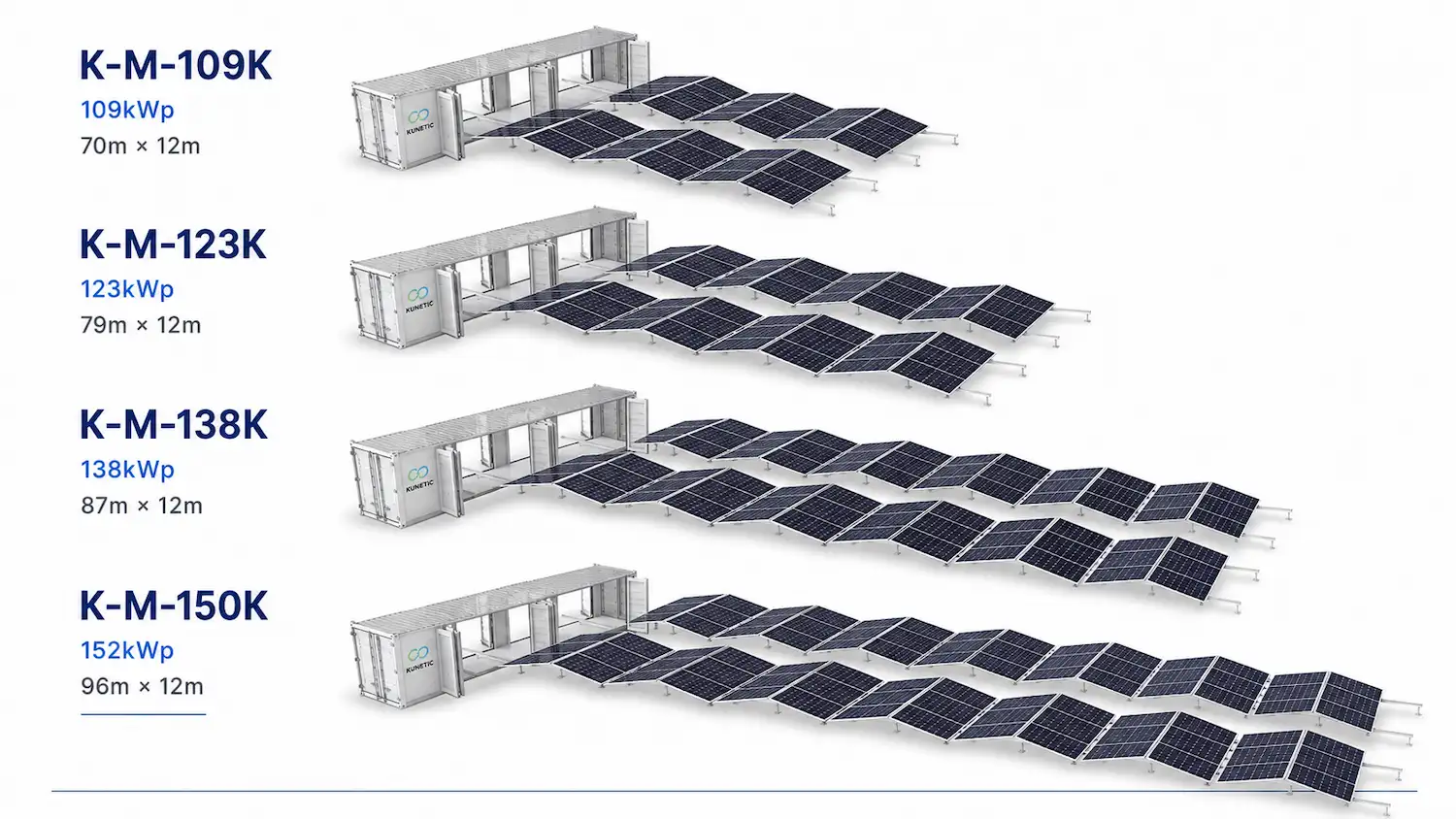
109kWp public PV value, 33t excluding storage and 70m × 12m deployed area.
123kWp public PV value, 34t excluding storage and 79m × 12m deployed area.
138kWp public PV value, 35t excluding storage and 87m × 12m deployed area.
152kWp public PV value, 36t excluding storage and 96m × 12m deployed area.
Reported Performance Indicators
The published figures below are presented as reported indicators, not universal project guarantees. Their comparison baselines and calculation methods are not stated, so they should be reviewed against the final site and operating plan.
Rail preparation, mechanical unfolding, connection and commissioning remain separate project stages.
Staffing requirements still depend on project scale and the operating plan.
The test set, sample size and validation method are not stated.
Actual economics depend on project location, solar resource, load profile and cost assumptions.
Applications
A relocatable container platform for projects that need packaged PV generation, battery storage and three-phase AC output.
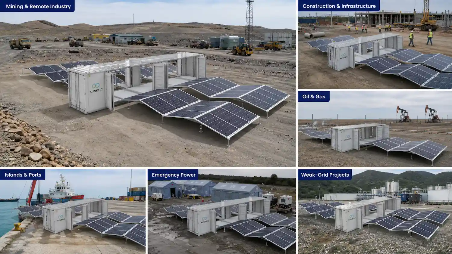
Deploy solar and storage near remote loads, then retract and relocate the system as the operating area or project stage changes.
Support temporary or phased site power where permanent infrastructure is not yet available. The container platform can move with the project.
Use a packaged solar and battery system for remote operating sites, with electrical and interface settings confirmed during engineering.
Combine container transport with on-site PV and storage for weak-grid or off-grid project loads.
Bring a packaged power system to locations where normal infrastructure is unavailable. Site preparation and commissioning requirements still apply.
Support temporary facilities and microgrid projects with selectable PV capacity and three-phase AC output.
Final selection depends on the load profile, solar resource, available footprint, electrical architecture, transport conditions and target-market requirements.
Project Configuration / OEM & ODM
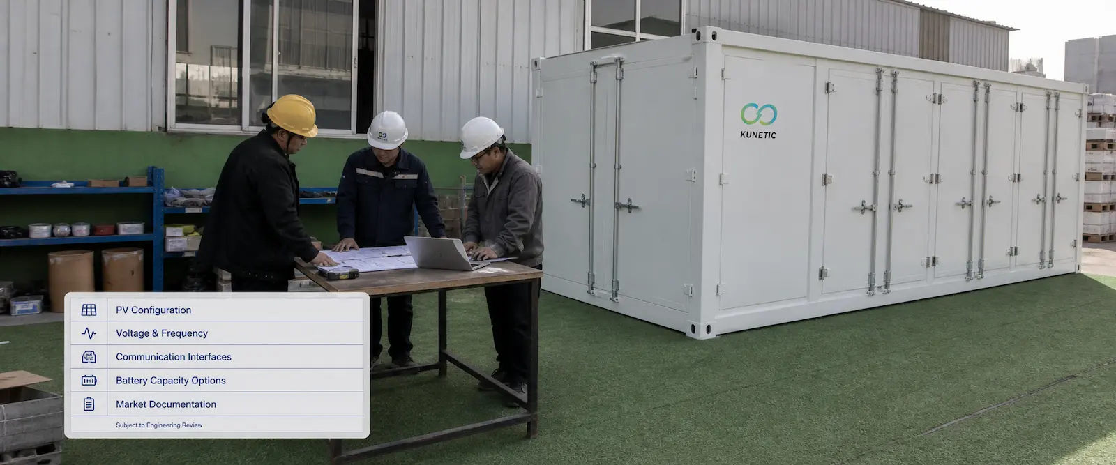
KUNETIC reviews the project before finalizing the system. The standard platform can be selected with one of four PV configurations. Electrical settings, optional communication interfaces, battery-capacity options and market documentation remain subject to engineering review.
Select 109, 123, 138 or 152kWp for the available site area and project demand. Exact PV values are confirmed in the technical configuration.
Configure 380V or 400V output and 50Hz or 60Hz operation within the approved system range.
Use RS485 as standard. CAN, ARC, PARA, USB, NTC, DRM and KIN are confirmed per project when required.
Capacity beyond the standard battery configuration is project-dependent and must be confirmed during engineering.
Confirm target-market certification, labels and technical documents for the selected model and destination.
Technical Specifications
Engineering data from the product sheet.
| K-M-109K PV capacity | 109.20kWp (±5%) |
| K-M-109K weight excluding storage | 33t |
| K-M-109K deployed area | 70m × 12m |
| K-M-123K PV capacity | 123.76kWp (±5%) |
| K-M-123K weight excluding storage | 34t |
| K-M-123K deployed area | 79m × 12m |
| K-M-138K PV capacity | 138.32kWp (±5%) |
| K-M-138K weight excluding storage | 35t |
| K-M-138K deployed area | 87m × 12m |
| K-M-150K PV capacity | 152.88kWp (±5%) |
| K-M-150K weight excluding storage | 36t |
| K-M-150K deployed area | 96m × 12m |
| Rated AC output power | 150kW |
| Inverter type | Hybrid inverter |
| Output voltage | 380V / 400V, 3L/N/PE |
| Output frequency | 50Hz / 60Hz |
| Battery chemistry | LFP |
| Standard battery capacity | 261kWh |
| Optional battery capacity | Project-dependent option, subject to confirmation |
| Cycle life | 5000 to 8000 cycles; DOD, temperature, rate and EOL conditions are not stated |
| Container material | Carbon steel |
| Container dimensions | 12192 × 2438 × 2896mm |
| Installation method | Lift and set down |
| Rail laying time | 15h |
| Deployment direction | Dual-side |
| Opening and closing | Electric |
| Locking mechanism | Manual |
| Mechanical unfolding time | ≤30 minutes after transport, site preparation, lifting and rail preparation |
| Cell technology | N-type TOPCon |
| Module power | 510 to 530W |
| Module dimensions | 1961 × 1134 × 30mm |
| Glass structure | 2.0mm tempered front glass + 2.0mm tempered rear glass |
| Frame | Anodized aluminium alloy |
| Module efficiency | ≥23% at STC |
| Module operating temperature | -40°C to +85°C |
| Module weight | 26.9kg |
| Support frame | Carbon steel, galvanized, zinc layer ≥55μm |
| Frame angle | 130° |
| Installation angle | 25° |
| Drive | Electric |
| Rail material | Zinc-aluminium-magnesium steel, coating ≥275g/m² |
| Adjustable support height | 50 to 80mm |
| Locking | Manual |
| Protection rating | IP55 in stowed state |
| Wind resistance | Level 9 after deployment; test standard not specified |
| Salt-fog resistance | ≤C5; test standard not specified |
| System operating temperature | -20°C to +50°C |
| System storage temperature | -20°C to +60°C, battery excluded |
| Standard communication | RS485 |
| Optional interfaces | CAN, ARC, PARA, USB, NTC, DRM, KIN |
| Certification list | CE (LVD / EMC / RoHS / ErP), TÜV, LPSR, PNS, ICC, SNI, TKDN, SABS, NERSA, GCC, SASO, ESMA |
| Electrical standards | IEC 60364, IEC 62548-1, IEC 60439-1, IEC 61643-21 |
| Mechanical standard | ISO 12100 |
| Market applicability | Certification and electrical applicability must be confirmed for the selected model and destination market |
 KUNETIC K-M-150K Mobile Off-Grid Solar System Datasheet
 Downloads
Request the KUNETIC datasheet for exact configuration tables, technical specifications, deployment references and project-evaluation information.
FAQ
The standard platform combines a carbon-steel container, a dual-side foldable PV array, a hybrid inverter, rated AC output, LFP battery storage, the support and rail system, and RS485 communication. Electrical settings and market-specific requirements are confirmed during project engineering.
The four options provide 109.20, 123.76, 138.32 or 152.88kWp of PV capacity. They also differ in product weight excluding storage and deployed area. All four retain the same rated AC output and standard battery platform.
The value covers mechanical unfolding after transport, site preparation, lifting and rail preparation are complete. It does not include rail laying, electrical connection, commissioning or full-site energization. Rail laying is listed separately as 15h.
The documented sequence includes lifting the container into position and laying the rail system before the PV array unfolds. Final site and connection requirements are confirmed during project engineering.
Yes. The array can be closed and the container prepared for transport to another project. Disconnection, loading, transport and preparation at the next site remain part of the relocation plan.
The approved output range is 380V or 400V, 3L/N/PE, at 50Hz or 60Hz. RS485 is standard. CAN, ARC, PARA, USB, NTC, DRM and KIN are optional and must be confirmed for the project.
The published value is 261kWh Standard Battery Capacity. Usable energy, DOD and battery-system voltage are not stated.
Certification is confirmed per model and destination market. Ask KUNETIC to verify the applicable certificate scope and supporting documents before ordering.
Tell us about your site load, PV capacity, backup requirements, or target project size. Our engineers will help configure the right system for your needs.
KUNETIC 150kW Mobile Off-Grid Solar System with 150kWp Foldable Solar Panels and 261kWh Battery Storage
Datasheet request
Request received. We will send the datasheet shortly.
KUNETIC 150kW Mobile Off-Grid Solar System with 150kWp Foldable Solar Panels and 261kWh Battery Storage
Product inquiry
Tell us about your site load, PV capacity, backup requirements, or target project size. Our engineers will help configure the right system for your needs.
Inquiry received. Our team will respond shortly.