
522kWh liquid-cooled LFP storage
Two 261kWh battery clusters provide 522kWh of rated energy. The battery uses 314Ah LFP cells with liquid cooling and heating.
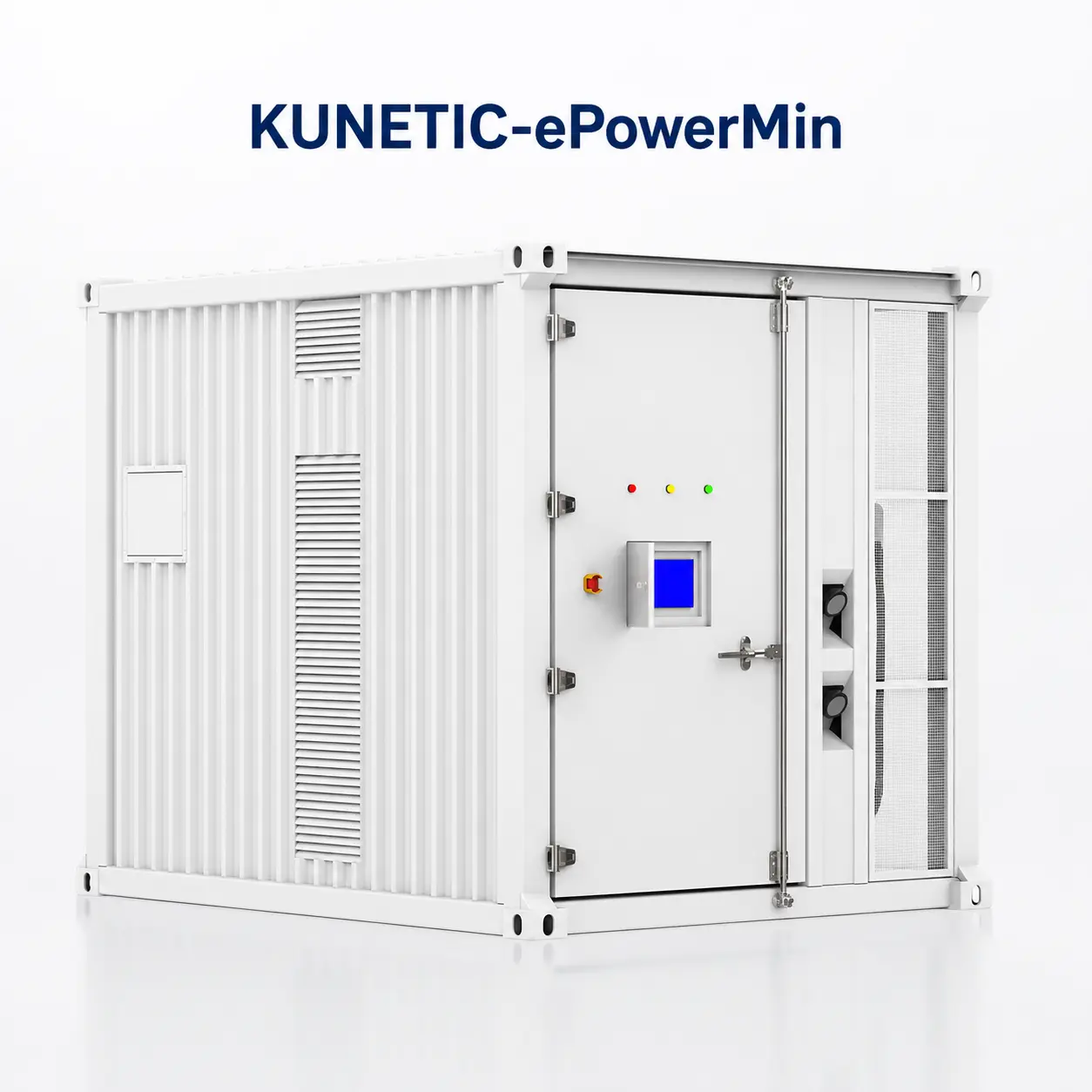
10ft PV + ESS + EV Charging System
Bring solar input, 522kWh of liquid-cooled LFP battery storage and 240kW DC EV charging into one transportable containerized system. The KUNETIC K-ePowerMini integrates a 250kW PCS, 180kW MPPT, EMS, two charging connectors and the main power-distribution equipment at the factory. It is intended for commercial EV charging stations, fleet depots, industrial sites, construction and mining projects, especially where the grid connection cannot supply the full charging load. The EMS coordinates solar, battery, grid and optional generator power, reducing field integration work and giving project teams more control over deployment.
 522kWh LFP Battery Storage
  250kW PCS Rated Power
  240kW DC EV Charging
  0ms Switching Time
 Overview
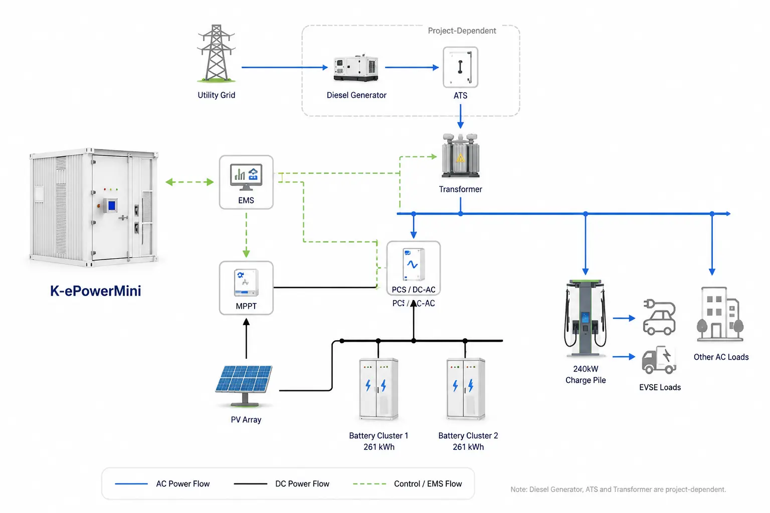
The KUNETIC K-ePowerMini packages two 261kWh liquid-cooled battery clusters, a 250kW PCS, 180kW MPPT input, EMS and a 240kW dual-connector DC charger in an approximately 10ft container. Its source topology includes solar PV, the utility grid and a diesel generator. The AC side can feed the EV charging equipment and other site loads. Source priority, transfer logic and site electrical interfaces are confirmed during project engineering. Because the main equipment is factory integrated, site teams have fewer separate enclosures and interfaces to coordinate. This reduces field cabling and commissioning compared with installing the battery, PCS, solar controller and EV chargers as independent systems. For more detail on containerized energy storage architecture, see our guide to BESS containers.
Limited grid capacity
When charging demand is higher than the available grid connection, the battery can supply part of the difference. Project engineers can then plan the charging site around the combined grid, PV and storage capacity rather than the instantaneous grid supply alone.
Complex equipment integration
The battery, PCS, MPPT, EMS and charging functions are coordinated within one platform. Site-side switchgear, transformer and generator interfaces still require project confirmation, but the main subsystems do not have to be integrated as separate products.
High and variable charging loads
The 522kWh battery acts as a buffer between available energy and charging demand. The EMS schedules solar generation, stored energy and grid power according to site load and the approved operating strategy.
Temporary or relocatable projects
The container can be shipped to a prepared site and redeployed later. It is not a handheld portable EV charger, a trailer-mounted product or a vehicle-mounted mobile EV charging unit designed to operate while moving.
Integrated Energy Architecture
The factory-integrated architecture reduces the number of separate systems that an EPC or site owner must coordinate. Each main function still has a clear electrical role.
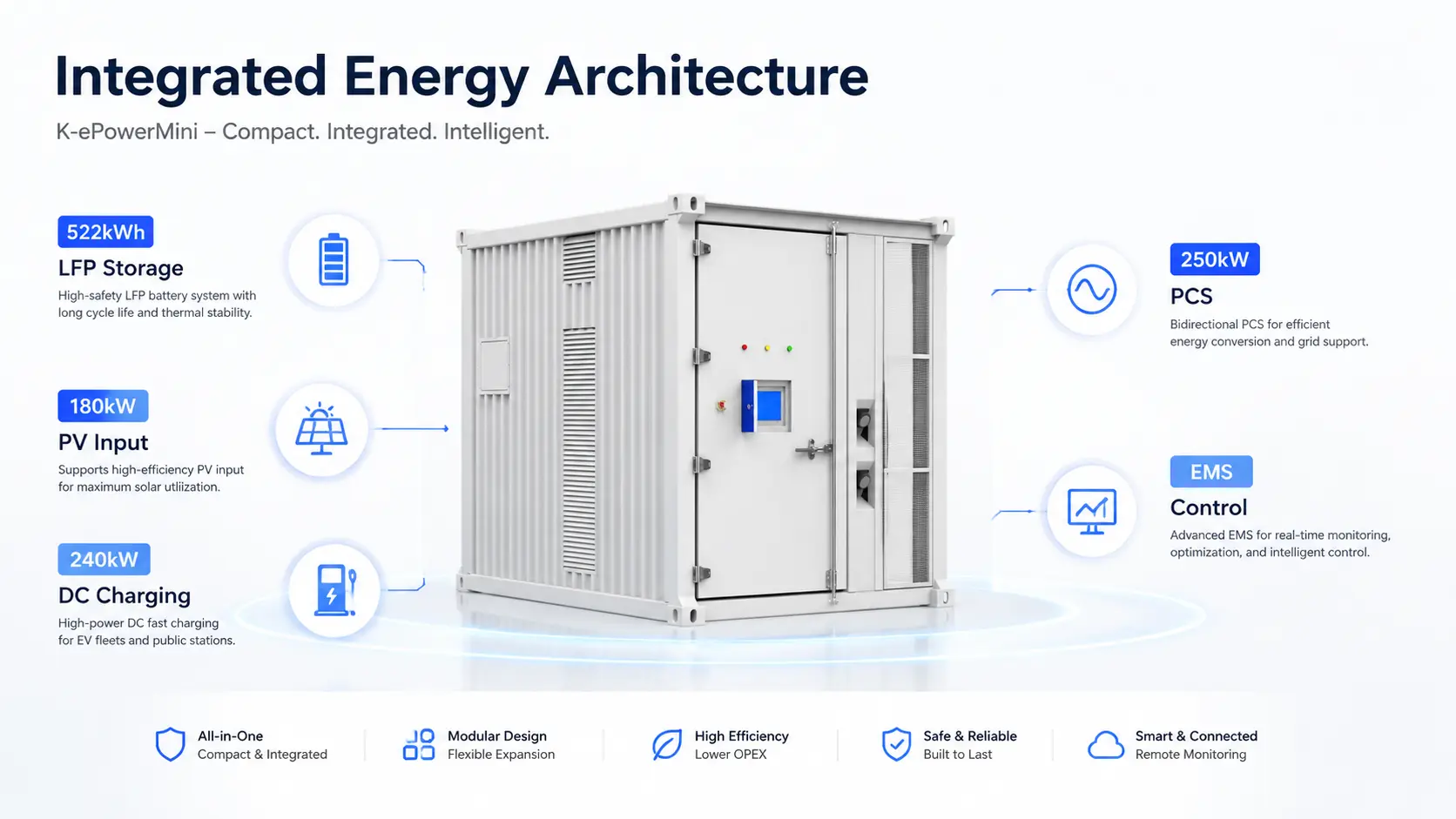
Two 261kWh battery clusters provide 522kWh of rated energy. The battery uses 314Ah LFP cells with liquid cooling and heating.
The PCS is rated at 250kW and converts power between the battery and the AC bus. It can supply up to 375kW for one minute as a short-duration overload condition.
The MPPT section accepts up to 180kW of PV input. Depending on the project controls, solar panels for EV charging can feed the charging load, support other AC loads or charge the battery.
The integrated DC EV charger provides 240kW of total charging power across two connectors. The power split depends on the selected charging modules, connected vehicles and project control strategy.
The EMS coordinates PV, battery, grid, diesel generation, EVSE and other AC loads. EV charging load management is configured around the grid connection, charging schedule and site priorities.
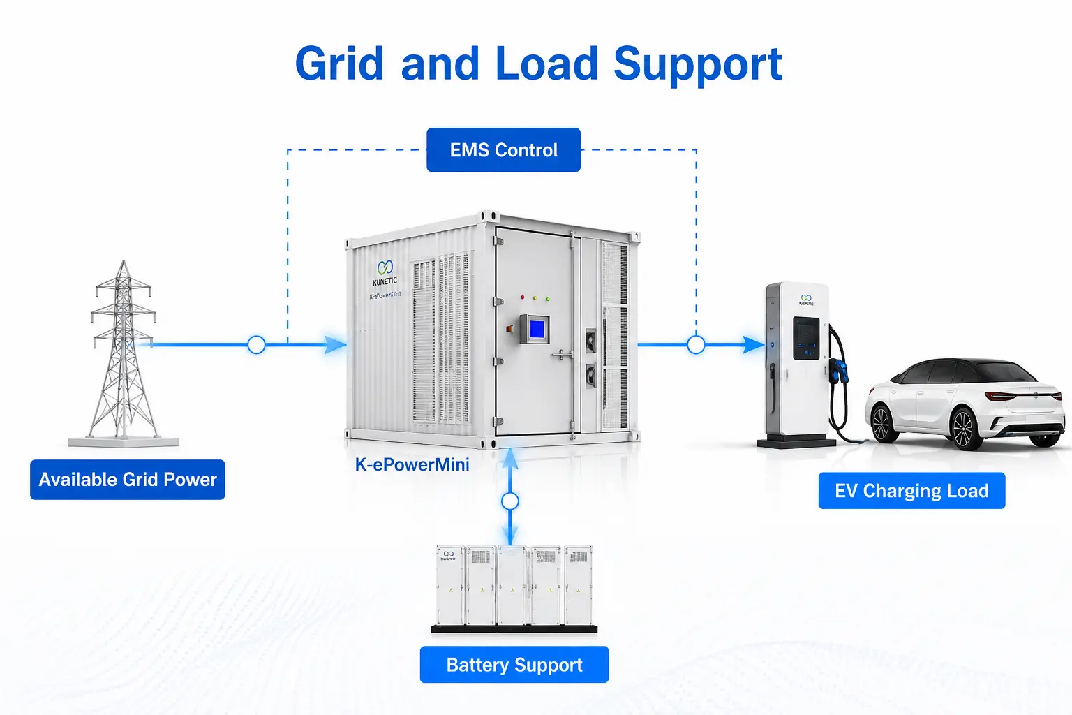
Grid and Load Support
Commercial charging sites may require more power than the grid can deliver at a given moment. Battery output can cover part of that gap within the limits of the stored energy, PCS rating and approved control strategy.
The specified architecture supports 0ms transfer in the approved operating configuration. Whether a particular load remains uninterrupted depends on the final electrical design, load characteristics, controls and commissioning.
The 250kW PCS can supply up to 375kW for one minute. This is a short-duration overload rating, not continuous output power.
The source topology includes an isolation transformer. Its final inclusion, voltage arrangement and electrical interface must be confirmed in the project BOM.
Liquid cooling and heating manage battery temperature. The source specification states a cell temperature difference below 3°C.
The battery is specified for more than 8,000 cycles at 25°C to 70% end of life.
Applications
Battery-supported charging for sites where the grid alone cannot efficiently meet the required load.
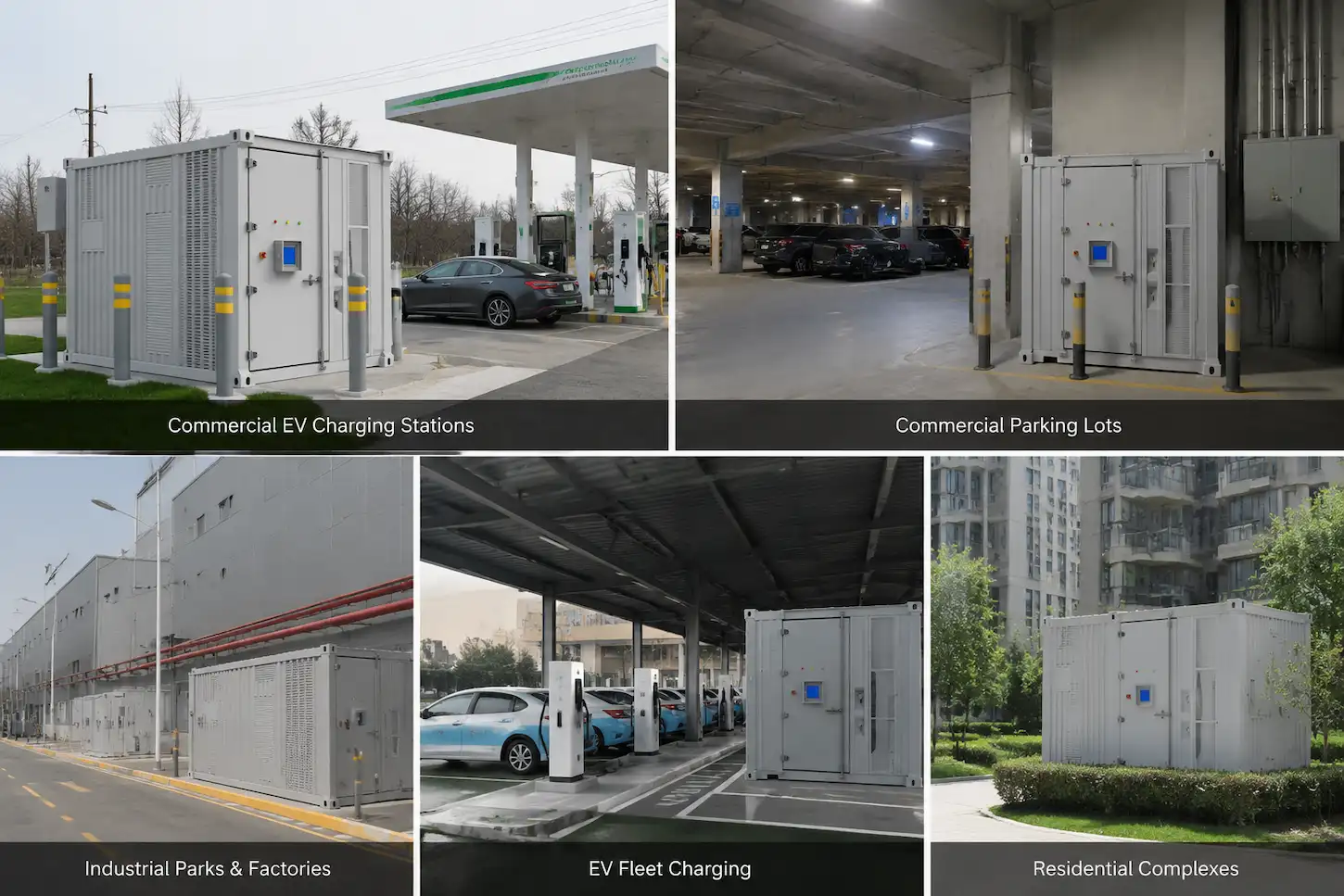
At parking areas, service locations and destination charging sites, the battery can supplement the grid during charging peaks and absorb available PV generation.
For EV fleet charging, the EMS can coordinate the charging schedule with available solar, battery and grid power. Typical vehicle groups include delivery vans, buses and other commercial fleets.
Factories and industrial parks can add charging while accounting for existing facility loads and limited spare grid capacity.
The container format suits temporary projects where the equipment may later move to another prepared site. Grid and diesel generator connections depend on the local infrastructure and approved electrical design.
At weak-grid or remote sites, battery storage can reduce the charging load placed on the grid at any one time. The final design still depends on available generation, storage duty cycle and site demand.
The K-ePowerMini is intended for projects that need commercial EV charging, local battery storage and solar integration in the same deployment. Explore the complete PV + ESS + EV charging solution for site topology, energy-flow planning and project-level system configuration.
Configured for Your Site
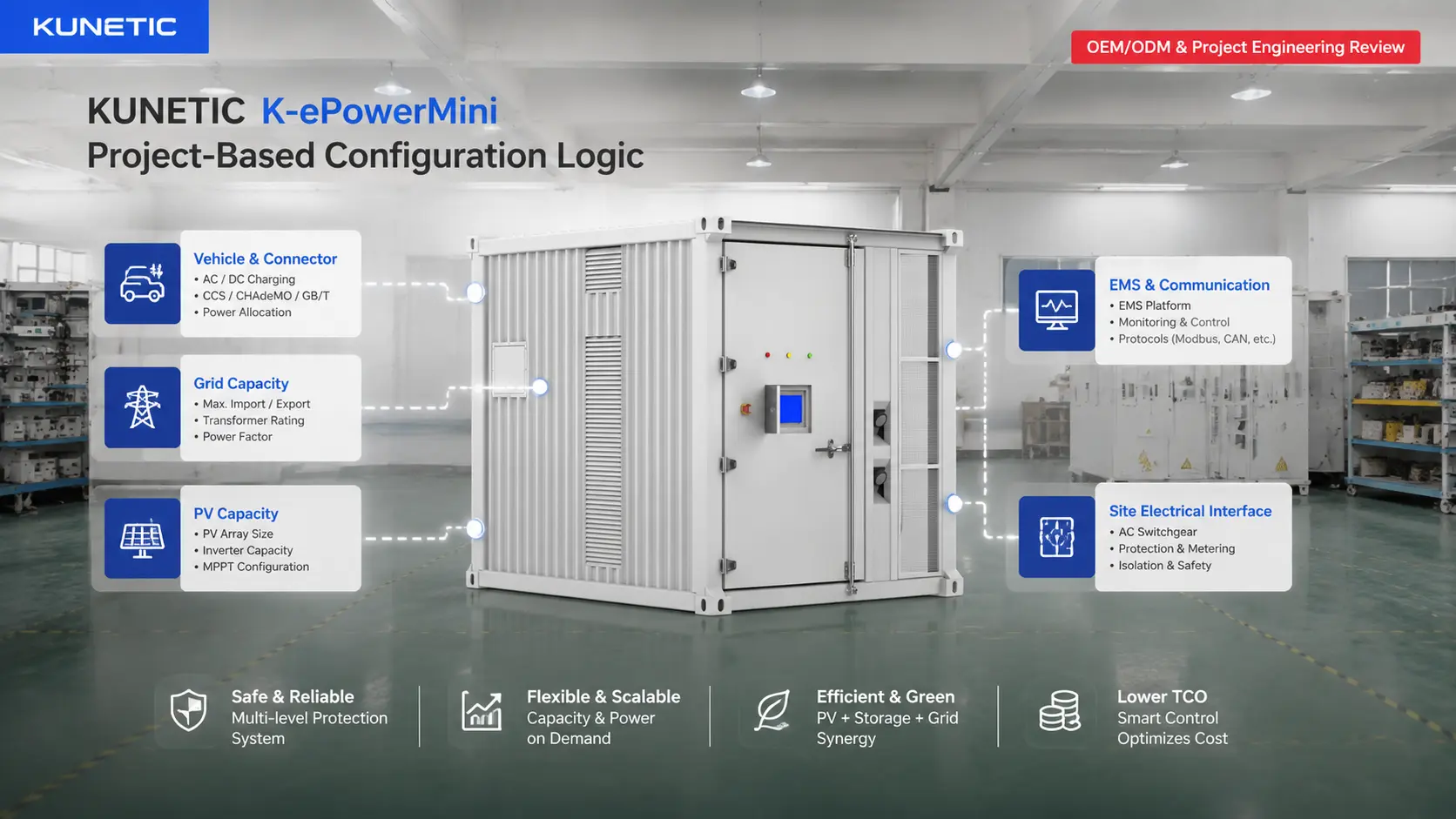
Vehicle type, connector requirement, grid capacity, available PV and charging schedule vary by project. KUNETIC confirms these inputs before the charging and electrical configuration is locked.
Connector hardware and communication requirements are selected for the target market and vehicle platform. The applicable charging standard must be confirmed before quotation and production.
The 240kW figure is the total charger rating, not 240kW per connector. Allocation between the two connectors depends on the selected modules, vehicle demand and control strategy.
The source architecture can include PV, grid and diesel generation. Project engineering sets the operating priority, transfer logic and permitted power flow for each source.
Monitoring, communication and site-level control requirements are confirmed against the customer's charging operation and energy-management needs.
The project design defines cable routing, connection points, transformer arrangement and the interface with the site's AC distribution system.
Technical Specifications
Engineering data from the product sheet.
| Battery chemistry | LFP |
| Cell capacity | 314Ah |
| Rated battery energy | 522kWh |
| Battery cluster configuration | 261kWh × 2 |
| Rated battery voltage | 832V |
| Maximum charge/discharge current | 200A × 2 |
| Thermal management | Liquid cooling and heating |
| Cell temperature difference | <3°C |
| Cycle life | >8,000 cycles at 25°C, 70% EOL |
| Rated PV / MPPT power | 180kW |
| Typical PV input voltage | 700V |
| Maximum PV input current | 135A × 3 |
| PCS rated power | 250kW |
| Short-duration overload | 375kW for 1 minute |
| Grid voltage | 230/400Vac |
| Grid frequency | 50Hz / 60Hz |
| Switching time | 0ms |
| Transformer | Project-dependent; source topology includes an isolation transformer |
| Supported energy inputs | PV, utility grid and diesel generator shown in source topology |
| Supported loads | EV charging and other AC loads |
| Total DC charging power | 240kW |
| Number of charging connectors | 2 |
| Maximum current per connector | 250A |
| Connector standard | Configured according to target market and project requirements |
| Power allocation | Project-based dynamic allocation |
| System format | Transportable containerized PV + ESS + EV charging system |
| Approximate container class | 10ft |
| Energy management | Integrated EMS |
| Main integrated equipment | Battery system, PCS, MPPT, EMS, EV charging, liquid cooling and related power-distribution functions |
| Project-dependent equipment | ATS, transformer arrangement and fire-system configuration subject to project confirmation |
| Protection rating | IP54 |
| Dimensions | 3050 × 2440 × 2590mm |
| Weight | Approximately 6850kg |
Downloads
The datasheet will cover the battery, PCS, PV input, EV charging, enclosure and project electrical interfaces.
FAQ
Yes. The battery clusters, PCS, MPPT, EMS and 240kW DC charger are factory integrated in one container. Site-side connections and project-dependent equipment still require engineering confirmation.
It is transportable, but it is not a handheld portable EV charger or a vehicle-mounted mobile EV charging product. Suitable lifting and transport equipment is required to move the container between prepared sites.
The source topology includes PV, grid and diesel generator inputs. Final connections, source priority and transfer logic are defined for each project.
Connector hardware and communication are selected for the target market, vehicle platform and applicable project requirements. The final standard is confirmed during technical design.
Battery storage can supply part of the charging demand when the required power is higher than the available grid connection. It can also store available solar energy for later charging or site use.
It is the specified transfer capability of the approved switching architecture. Actual performance depends on the final electrical design, supported loads, controls and commissioning.
Tell us about your site load, PV capacity, backup requirements, or target project size. Our engineers will help configure the right system for your needs.
KUNETIC 522kWh Containerized Solar EV Charging Station with 240kW DC Fast Charging
Datasheet request
Request received. We will send the datasheet shortly.
KUNETIC 522kWh Containerized Solar EV Charging Station with 240kW DC Fast Charging
Product inquiry
Tell us about your site load, PV capacity, backup requirements, or target project size. Our engineers will help configure the right system for your needs.
Inquiry received. Our team will respond shortly.