Table of Contents
What Is a Solar-Storage Integrated System?
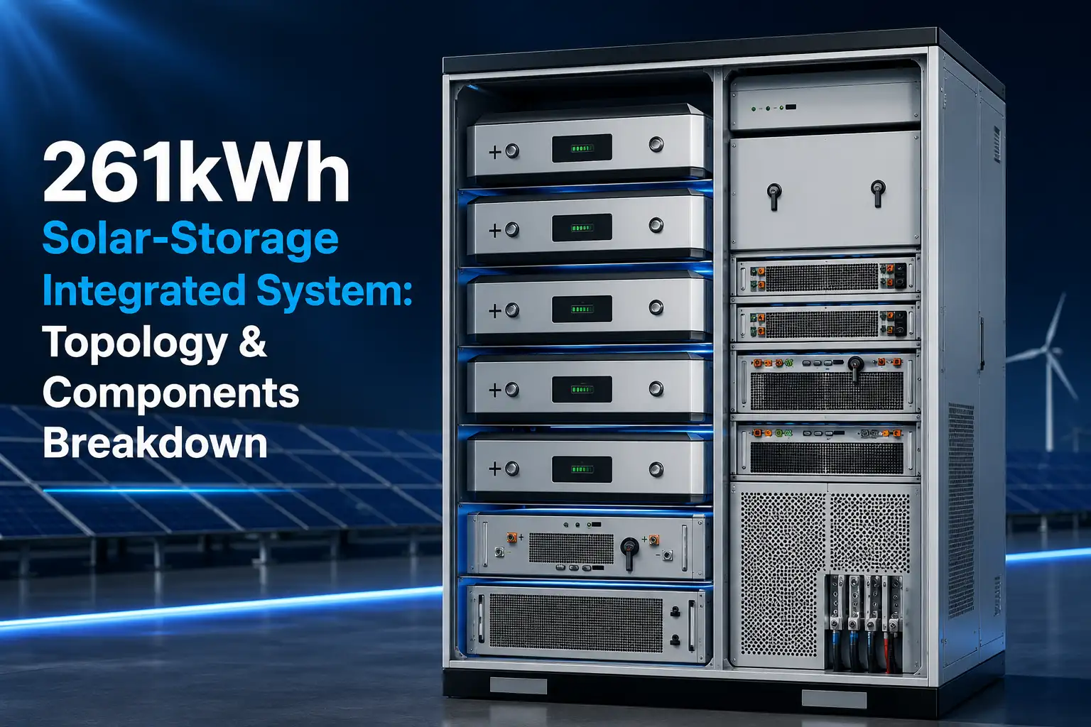
A solar-storage integrated system puts PV and battery storage into one DC-coupled container. Normally, solar and storage go in as two separate units, each with its own inverter. This setup connects both to a shared DC bus instead. For fundamentals, see our BESS complete guide.
Dropping one AC-DC conversion stage does two things: it cuts hardware cost, and it adds 3 to 5 percent to round-trip efficiency.
This 261kWh unit fits in a standard 20-foot container. It targets commercial and industrial sites — factories, warehouses, remote facilities. These sites use renewable energy sources paired with battery storage to reduce electricity costs and gain energy independence.
Unlike standalone battery storage solutions, a PV ESS integrated system combines solar and storage in one container. For commercial energy storage and industrial battery storage projects, this cuts installation time compared to deploying separate PV and energy storage units on site.
DC-Coupled Topology
Why DC-Coupled Over AC?
In an AC-coupled system, PV systems feed a solar inverter that produces alternating current (AC). The battery has its own inverter, charging from the same AC bus. Power goes through two conversions before it reaches the battery: DC to AC, then AC back to DC. That second conversion wastes energy. The IEA provides an overview of how BESS architectures compare in real-world deployments.
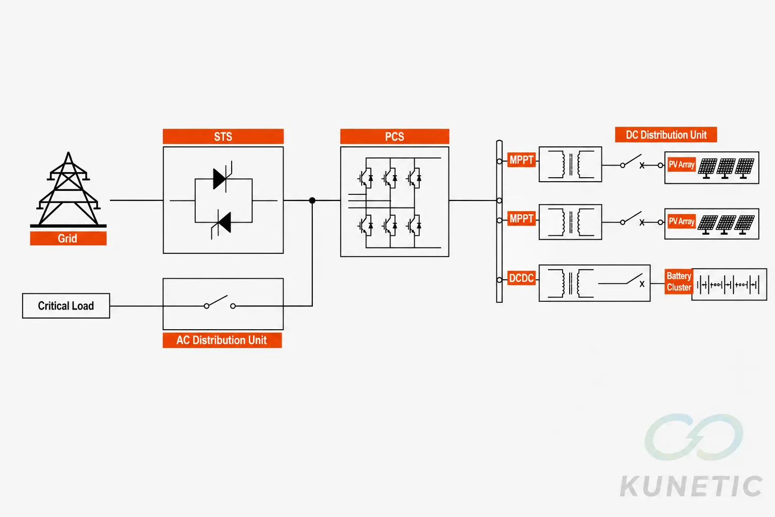
A DC-coupled solar storage system topology avoids it. The PV array and the battery share a common DC bus.
Power flows from PV panels to the DC bus through an MPPT module. From the DC bus to the battery, it goes through a separate DC-DC converter. One inverter — the PCS — handles the DC-to-AC job for the grid connection.
Fewer conversions. Fewer components. Higher system efficiency.
Power Flow
Electricity moves through the system along this path:
PV Array → MPPT Module → 750Vdc DC Bus
Battery Pack ↔ DCDC Converter ↔ 750Vdc DC Bus
750Vdc DC Bus → PCS (DC/AC) → AC Load / Grid
The 750Vdc bus is the backbone. Every DC source and load ties into it. The PCS is the single point where DC becomes AC.
An optional STS (Static Transfer Switch) sits between the PCS and the electricity grid. If the grid goes down, it disconnects the system in under 10ms.
Component-by-Component Breakdown
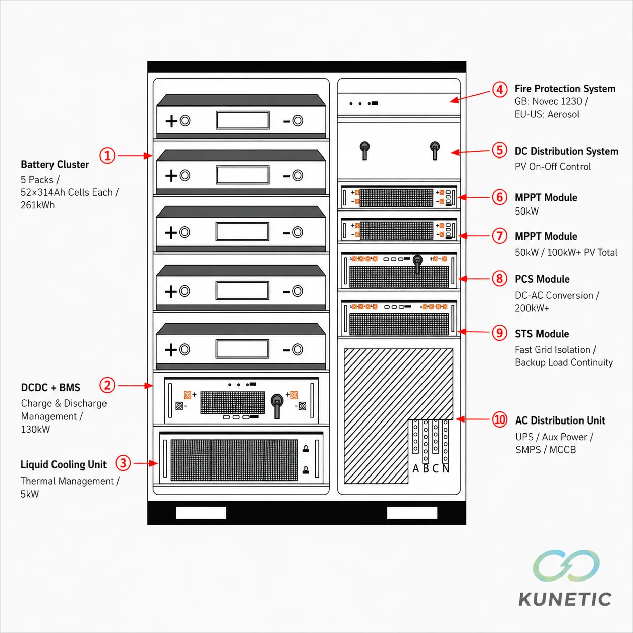
The BESS components inside the container break down into seven core subsystems. Each one serves a specific function within the DC-coupled architecture. Like other energy storage technologies, the design prioritises thermal safety and electrical isolation between subsystems. See our BESS container guide for more on containerised storage design.
Battery Cluster — 5P × 52S × 314Ah
Five packs, wired in parallel. Inside each pack, 52 LFP lithium-ion battery cells in series. Each cell: 314Ah at 3.2V nominal.
Multiply it out: 5 × 52 × 314Ah × 3.2V = 261kWh.
LFP is the standard choice for stationary C&I storage. Lower energy density than NMC, but far better thermal stability and cycle life. At 0.5C charge/discharge, expect 6,000+ cycles.
DCDC Converter + BMS — 130kW
A 130kW DC-DC converter sits between the battery cluster and the 750Vdc bus. Two jobs: stepping voltage up or down to match the bus, and managing charge and discharge current.
This module houses the battery management system (BMS). It watches cell voltage, temperature, and state of charge across all 260 cells. If any cell drifts outside safe limits, the BMS tells the DCDC to throttle or disconnect.
Liquid Cooling — 5kW Thermal Management
A 261kWh cluster generates real heat during charge and discharge.
This unit runs a dedicated liquid cooling loop rated at 5kW. A self-contained chiller circulates coolant through cold plates mounted on the battery modules.
For C&I systems at this scale, liquid beats air cooling in two ways:
Tighter cell temperatures across the pack, which slows degradation.
More efficient heat removal from a sealed container.
Air cooling in a 20-foot box needs large intake and exhaust openings. Those openings make IP rating and fire containment harder to design.
Fire Suppression — Perfluorohexanone vs Aerosol
The suppression method depends on which standard the installation follows. System design references IEC 62933, the international standard for electrical energy storage systems.
Under GB (Chinese national standard) requirements, the system uses perfluorohexanone (FK-5-1-12). This clean agent puts out fires by absorbing heat.
Under European and other international standards, the system uses aerosol-based suppression.
Both are total-flooding designs. The agent fills the sealed battery compartment. A thermal runaway event cannot spread without the right conditions, and the agent denies those conditions. The medium changes with the market. The safety philosophy underneath stays the same.
MPPT Modules — 2×50kW
Two MPPT solar storage modules, each 50kW, give the system 100kW+ of PV input.
Each module tracks its connected PV strings independently. As sunlight levels and temperature change, it adjusts the DC-DC conversion ratio in real time. MPPT outputs go straight to the 750Vdc bus.
String-level tracking means shade on one string does not pull down the output of the others. That matters on commercial rooftops where HVAC units, vents, and neighbouring buildings create uneven shading through the day.
PCS — 200kW+ Two-Way Inverter
The Power Conversion System is the bridge between the DC bus and the AC side.
Rated at 200kW+, it handles power in both directions:
DC to AC when discharging to grid or load.
AC to DC if the system ever charges from the grid.
In grid-tied mode, the PCS locks to grid frequency and voltage. In off-grid mode, the PCS creates its own voltage and frequency reference for the islanded microgrid once the STS opens.
STS, DC & AC Distribution
The STS sits between the PCS output and the grid connection point. If the grid faults, it opens the connection in under 10 milliseconds. This blocks back-feed into a dead grid while the system keeps powering local loads.
On the DC side, a distribution unit handles switching and protection for the PV input circuits.
On the AC side, a distribution panel houses the UPS, switch-mode power supplies, molded-case circuit breakers (MCCBs), and other AC components. Together these units route, protect, and power the container's internal electrical needs.
Four Operation Modes
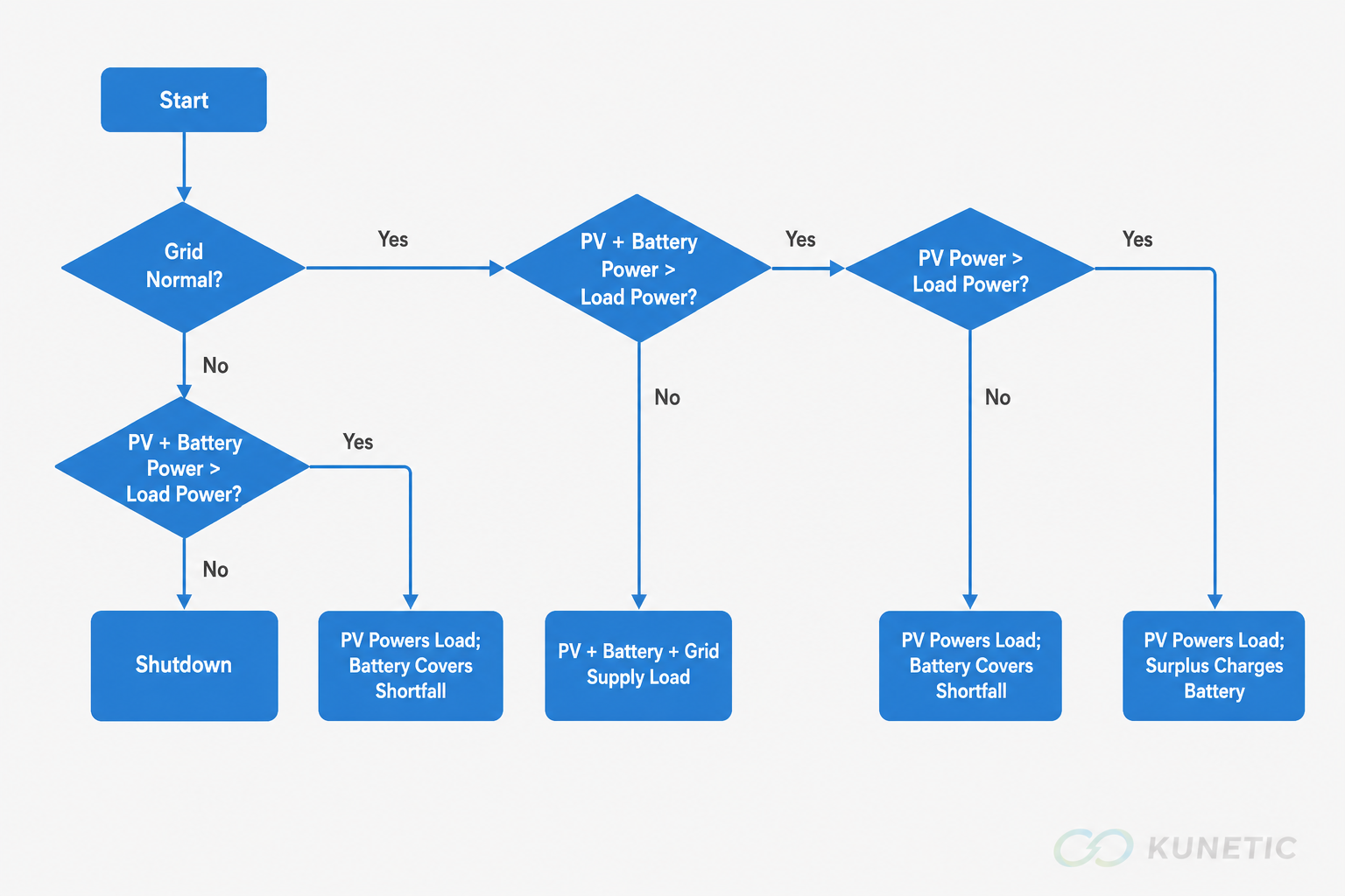
The energy management system (EMS) picks from four modes. It decides based on grid status, PV output, battery state of charge, and load demand.
Mode 1. Off-Grid (Grid Fault)
Grid fails. STS opens within 10ms. System islanded. PV powers the load first. Surplus goes to the battery.
If PV alone cannot meet the load, the battery fills the gap.
If PV plus battery still fall short of the load, the system shuts down. This protects the battery from over-discharge.
This mode also covers sites with no grid connection at all.
Mode 2. Grid Normal, PV Surplus
Grid healthy, PV output exceeds the load. The system powers the load first. Whatever the load does not use charges the battery. No grid export unless the operator has configured it — a separate control decision.
Mode 3. Grid Normal, PV + Battery Combined
Grid healthy, but PV alone falls short of load. The battery fills the gap, discharging only what is needed. This mode runs as long as PV plus battery together can meet the load.
Mode 4. Grid Normal, All Sources
Grid healthy, PV plus battery still cannot cover the load — nighttime with a discharged battery, for example. The grid supplies the remaining shortfall. All three sources, PV, battery, and grid, run at once.
# | Grid Status | Condition | Power Source Priority |
1 | Off-grid | Grid fault or no grid | 1. PV 2. Battery. Stop if PV+Batt < Load |
2 | Normal | PV > Load | 1. Load 2. Charge Battery |
3 | Normal | PV < Load, PV+Batt >= Load | 1. PV 2. Battery supplement |
4 | Normal | PV+Batt < Load | 1. PV 2. Battery 3. Grid supplement |
These four modes describe the base logic. Real sites often add time-of-use tariff optimisation and peak-shaving schedules on top. This article does not cover those control strategies.
Key Specifications at a Glance
Subsystem | Parameter | Value |
Battery Cluster | Configuration | 5 packs × 52 cells × 314Ah |
Battery Cluster | Total Capacity | 261 kWh |
Battery Cluster | Cell Chemistry | LFP (LiFePO₄) |
DCDC Converter | Rated Power | 130 kW |
DCDC Converter | Function | Charge/discharge + integrated BMS |
MPPT Modules | Quantity × Power | 2 × 50 kW (100 kW+ total) |
PCS | Rated Power | 200 kW+ |
PCS | Type | Two-way DC/AC |
DC Bus | Voltage | 750 Vdc |
Liquid Cooling | Cooling Capacity | 5 kW |
Fire Suppression | GB Standard | Perfluorohexanone (FK-5-1-12) |
Fire Suppression | EU/International | Aerosol |
STS | Switching Speed | <10 ms |
AC Distribution | Components | UPS, auxiliary PSU, MCCBs |
Summary
The 261kWh system packs six core subsystems into one container — a self-contained energy storage solution for commercial and industrial sites:
A 261kWh LFP lithium-ion battery cluster
A 130kW DCDC converter with integrated battery management system
Dual 50kW MPPT modules
A 200kW+ two-way PCS
Liquid cooling
Fire suppression
All tied to a 750Vdc common bus with an STS for grid-to-off-grid transition. These are the energy storage system components that make up a complete commercial solar storage and commercial battery storage systems unit. For help selecting the right configuration, see our C&I energy storage buyer's guide.
For project-specific technical data, contact KUNETIC's engineering team.
FAQ
DC-Coupled vs AC-Coupled — What Is the Difference?
DC-coupled: PV and battery share a DC bus behind one inverter, so power only goes through one conversion stage to reach the battery. AC-coupled: PV and battery each have their own inverter, so power hits two conversion stages. DC-coupled has fewer components and roughly 3 to 5 percent higher round-trip efficiency. AC-coupled is easier to retrofit onto existing solar.
How Long Can a 261kWh System Run a Commercial Load?
A 50kW load pulls about 50kWh per hour. From a full battery, that is 4 to 5 hours. With PV adding power during the day, runtime stretches further. Real numbers depend on the load profile, PV output, and depth of discharge limits. For sites looking to reduce energy consumption during peak-rate hours, the system can be programmed to prioritise battery discharge when grid electricity is most expensive.
Can It Run Fully Off-Grid?
Yes. The STS disconnects from the grid and the PCS forms an islanded microgrid. PV and battery cover the load. For sites with no grid at all, add a diesel generator as backup for extended low-PV periods.
What Fire Safety Standards Apply?
Perfluorohexanone (FK-5-1-12) under GB standards. Aerosol-based systems under European and other international standards. Both use total-flooding: the agent fills the sealed battery compartment. Temperature sensors and the BMS give early warning before suppression kicks in.
What Maintenance Does Liquid Cooling Need?
Quarterly: coolant level, glycol concentration, cold plate connections for leaks, chiller air filters, pump and fan check. Annually: fire suppression test, STS switching time verification, full battery capacity check. The BMS tracks cell health constantly and flags anything between inspections.